
Description of the game
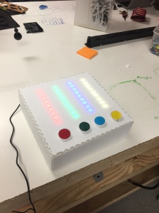
Our group’s game took the basic concept’s of simon says and formed an electronic game that tests a player’s memory. Inspiration for the game came from the handheld game “Simon”, which requires players to watch the light pattern it plays and then recreate the pattern by pushing the corresponding buttons in the right order. Once a player completes the pattern, the game plays the same pattern but this time with an added sequence part. Our game behaves in the same way, however ours has a different physical format and does not contain a sound element as the “simon” game does. Pictured below is the final result of our Simon Says game which has an exterior made of foam core that is thinned out in the areas where the led lights shine through and holds 4 buttons along the bottom edge that correspond with the colors of the lights above them.
 When the game begins it plays a sequence of 5 lights and then waits with all lights off for the player to press the buttons in the same sequence as the light pattern. If the player gets one wrong all of the lights turn on signaling that the player has lost. If the player gets the pattern right the same sequence plays again, this time adding one more piece to the pattern. The player then tries again to recreate the pattern and the game goes on. The sequence can get up to 105 steps from it’s original 5 steps.
Pictured below is the inner components of the game. The components are connected on a breadboard and some by way of soldering. The neo-pixels are taped to the foam core and then plug into the breadboard. The buttons are lose in this picture and not fixed in their final locations yet so that the inner workings can be better viewed.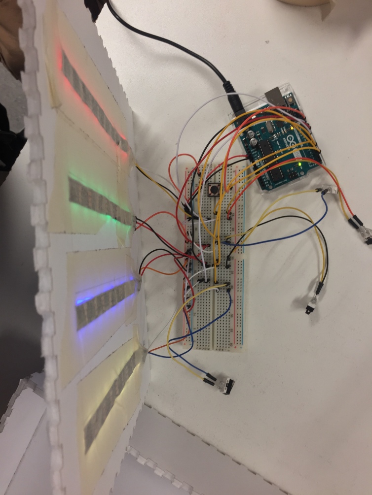
Input & output elements
The input elements for the game are simply the four buttons which are read in the code and used to determine the player’s status in the game. The output elements for the game are the four neo-pixel lights that we used to create the patterns and give us a way to communicate the game state with the player.
Construction
As can be seen in the picture above, the jumper wires are used to connect the components to each other using the bread board and soldering. Most components were simply put in place in the breadboard, however, the buttons were soldered to jumper wires to allow us to place them farther away from the bread board in the final composition. As for the enclosure, it is made of foam core that was laser cut using a template created online with a website that uses dimensions to create box templates. 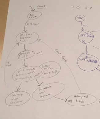
Software
The software for our game consists of 5 states: “start”, “SEQ_DISPLAY”, “SEQ_OFF”, “USER_SELECT”, and “USER_REPEAT”. Theses states were used to create a state machine from an original state diagram that we created (pictured above). The states are coordinated using several series of “If” and “Else if” statements. Pictured below is just a small portion of the code which displays the variable setup that comes before the actual “setup” function of the code.
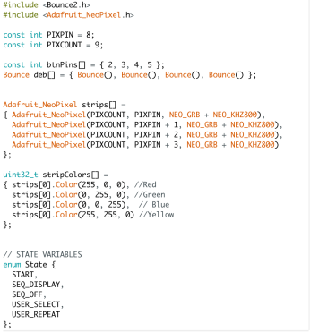
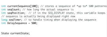
This overall variable and state setup gives a picture of what the rest of the code looks like; i.e. what methods were used to create the software. So, following this setup comes the “setup” function and then the “loop” which contains the “if” and “else if” features that coordinate the states. This software combined with the hardware discussed above are what we were able to combine to create our final simon says game.
My group consisted of myself, Graham, Will K., and Hunter.
